
- August 1, 2021
- Posted by: team SOUTECH
- Category: Blog, Blogging, CEH, CISCO, CISSP, Cyber-security and Ethical Hacking Training, cyberOps, Ethical Hacking and Kali Linux Free Training, Intelligence, Security, Wireshark
Mininet Topology
Objectives
Part 1: Examine the Header Fields in an Ethernet II Frame
Part 2: Use Wireshark to Capture and Analyze Ethernet Frames
Background / Scenario
When upper layer protocols communicate with each other, data flows down the Open Systems Interconnection (OSI) layers and is encapsulated into a Layer 2 frame. The frame composition is dependent on the media access type. For example, if the upper layer protocols are TCP and IP and the media access is Ethernet, then the Layer 2 frame encapsulation will be Ethernet II. This is typical for a LAN environment.
When learning about Layer 2 concepts, it is helpful to analyze frame header information. In the first part of this lab, you will review the fields contained in an Ethernet II frame. In Part 2, you will use Wireshark to capture and analyze Ethernet II frame header fields for local and remote traffic.
Required Resources
- CyberOps Workstation virtual machine
Instructions
Part 1: Examine the Header Fields in an Ethernet II Frame
In Part 1, you will examine the header fields and content in an Ethernet II Frame provided to you. A Wireshark capture will be used to examine the contents in those fields.
Step 1: Review the Ethernet II header field descriptions and lengths.
| Preamble | Destination Address |
Source Address |
Frame Type |
Data | FCS |
| 8 Bytes | 6 Bytes | 6 Bytes | 2 Bytes | 46 – 1500 Bytes | 4 Bytes |
Step 2: Examine Ethernet frames in a Wireshark capture.
The Wireshark capture below shows the packets generated by a ping being issued from a PC host to its default gateway. A filter has been applied to Wireshark to view the ARP and ICMP protocols only. The session begins with an ARP query for the MAC address of the gateway router, followed by four ping requests and replies.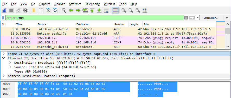
Step 3: Examine the Ethernet II header contents of an ARP request.
The following table takes the first frame in the Wireshark capture and displays the data in the Ethernet II header fields.
| Field | Value | Description |
| Preamble | Not shown in capture | This field contains synchronizing bits, processed by the NIC hardware. |
| Destination Address
Source Address |
Broadcast (ff:ff:ff:ff:ff:ff)
IntelCor_62:62:6d (f4:8c:50:62:62:6d) |
Layer 2 addresses for the frame. Each address is 48 bits long, or 6 octets, expressed as 12 hexadecimal digits, 0-9,A-F. A common format is 12:34:56:78:9A:BC.The first six hex numbers indicate the manufacturer of the network interface card (NIC), the last six hex numbers are the serial number of the NIC. The destination address may be a broadcast, which contains all ones, or a unicast. The source address is always unicast. |
| Frame Type | 0x0806 | For Ethernet II frames, this field contains a hexadecimal value that is used to indicate the type of upper-layer protocol in the data field. There are numerous upper-layer protocols supported by Ethernet II. Two common frame types are:
Value Description 0x0800 IPv4 Protocol 0x0806 Address resolution protocol (ARP) |
| Data | ARP | Contains the encapsulated upper-level protocol. The data field is between 46 – 1,500 bytes. |
| FCS | Not shown in capture | Frame Check Sequence, used by the NIC to identify errors during transmission. The value is computed by the sending machine, encompassing frame addresses, type, and data field. It is verified by the receiver. |
Questions:
What is significant about the contents of the destination address field?
All hosts on the LAN will receive this broadcast frame. The host with the IP address of 192.168.1.1 (default gateway) will send a unicast reply to the source (PC host). This reply contains the MAC address of the NIC of the Default Gateway.
Why does the PC send out a broadcast ARP prior to sending the first ping request?
Before the PC can send a ping request to a host, it needs to determine the destination MAC address before it can build the frame header for that ping request. The ARP broadcast is used to request the MAC address of the host with the IP address contained in the ARP.
What is the MAC address of the source in the first frame?
f4:8c:50:62:62:6d
What is the Vendor ID (OUI) of the Source’s NIC?
IntelCor (Intel Corporation)
What portion of the MAC address is the OUI?
The first 3 octets of the MAC address indicate the OUI.
What is the Source’s NIC serial number?
62:62:6d
Part 2: Use Wireshark to Capture and Analyze Ethernet Frames
In Part 2, you will use Wireshark to capture local and remote Ethernet frames. You will then examine the information that is contained in the frame header fields.
Step 1: Examine the network configuration of H3.
- Start and log into your CyberOps Workstation VM using the following credentials:
Username: analyst Password: cyberops
- Open a terminal emulator to start mininet and enter the following command at the prompt. When prompted, enter cyberops as the password.
[analyst@secOps ~]$ sudo ./lab.support.files/scripts/cyberops_topo.py
[sudo] password for analyst:
- At the mininet prompt, start terminal windows on host H3.
*** Starting CLI:
mininet> xterm H3
- At the prompt on Node: h3, enter ip address to verify the IPv4 address and record the MAC address.
| Host-interface | IP Address | MAC Address |
| H3-eth0 | 10.0.0.13 | Answers may vary. |
- At the prompt on Node: H3, enter netstat -r to display the default gateway information.
[root@secOps ~]# netstat -r
Kernel IP routing table
Destination Gateway Genmask Flags MSS Window irtt Iface
default 10.0.0.1 0.0.0.0 UG 0 0 0 H3-eth0
10.0.0.0 0.0.0.0 255.255.255.0 U 0 0 0 H3-eth0
Question:
What is the IP address of the default gateway for the host H3?
10.0.0.1
Step 2: Clear the ARP cache on H3 and start capturing traffic on H3-eth0.
- In the terminal window for Node: H3, enter arp -n to display the content of the ARP cache.
[root@secOps analyst]# arp -n
- If there is any existing ARP information in the cache, clear it by enter the following command: arp -d IP-address. Repeat until all the cached information has been cleared.
[root@secOps analyst]# arp -n
Address HWtype HWaddress Flags Mask Iface
10.0.0.11 ether 5a:d0:1d:01:9f:be C H3-eth0
[root@secOps analyst]# arp -d 10.0.0.11
Address HWtype HWaddress Flags Mask Iface
10.0.0.11 (incomplete) C H3-eth0
- In the terminal window for Node: H3, open Wireshark and start a packet capture for H3-eth0 interface.
[root@secOps analyst]# wireshark-gtk &
Step 3: Ping H1 from H3.
- From the terminal on H3, ping the default gateway and stop after send 5 echo request packets.
[root@secOps analyst]# ping -c 5 10.0.0.1
- After the ping is completed, stop the Wireshark capture.
Step 4: Filter Wireshark to display only ICMP traffic.
Apply the icmp filter to the captured traffic so only ICMP traffic is shown in the results.
Step 5: Examine the first Echo (ping) request in Wireshark.
The Wireshark main window is divided into three sections: the Packet List pane (top), the Packet Details pane (middle), and the Packet Bytes pane (bottom). If you selected the correct interface for packet capturing in Step 3, Wireshark should display the ICMP information in the Packet List pane of Wireshark, similar to the following example.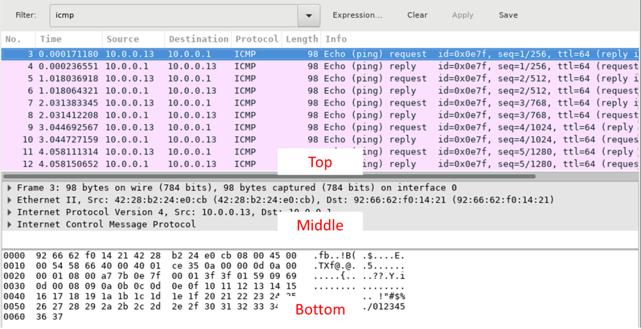
- In the Packet List pane (top section), click the first frame listed. You should see Echo (ping) request under the Info This should highlight the line blue.
- Examine the first line in the Packet Details pane (middle section). This line displays the length of the frame; 98 bytes in this example.
- The second line in the Packet Details pane shows that it is an Ethernet II frame. The source and destination MAC addresses are also displayed.
Questions:
What is the MAC address of the PC’s NIC?
42:28:b2:24:e0:cb in example
What is the default gateway’s MAC address?
92:66:62:f0:14:21 in example
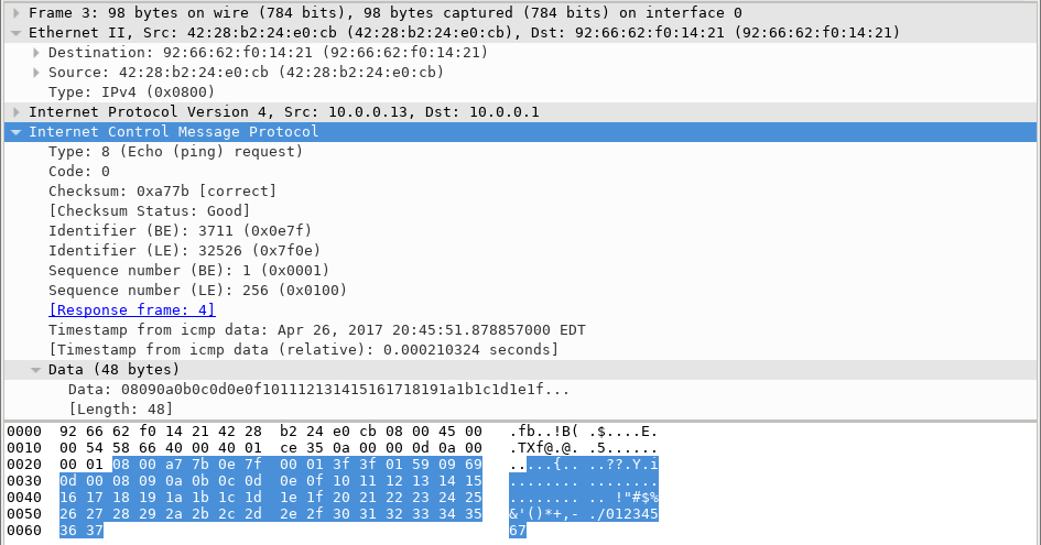
- You can click the arrow at the beginning of the second line to obtain more information about the Ethernet II frame.
Question:
What type of frame is displayed?
0x0800 or an IPv4 frame type.
- The last two lines displayed in the middle section provide information about the data field of the frame. Notice that the data contains the source and destination IPv4 address information.
Questions:
What is the source IP address?
10.0.0.13 in the example
What is the destination IP address?
10.0.0.1 in the example
- You can click any line in the middle section to highlight that part of the frame (hex and ASCII) in the Packet Bytes pane (bottom section). Click the Internet Control Message Protocol line in the middle section and examine what is highlighted in the Packet Bytes pane.
- Click the next frame in the top section and examine an Echo reply frame. Notice that the source and destination MAC addresses have reversed, because this frame was sent from the default gateway router as a reply to the first ping.
Question:
What device and MAC address is displayed as the destination address?
The host H3, 42:28:b2:24:e0:cb in example.
Step 6: Start a new capture in Wireshark.
- Click the Start Capture icon to start a new Wireshark capture. You will receive a popup window asking if you would like to save the previous captured packets to a file before starting a new capture. Click Continue without Saving.
- In the terminal window of Node: H3, send 5 echo request packets to 172.16.0.40.
- Stop capturing packets when the pings are completed.
Step 7: Examine the new data in the packet list pane of Wireshark.
Questions:
In the first echo (ping) request frame, what are the source and destination MAC addresses?
Source:
This should be the MAC address of the PC.
Destination:
This should be the MAC address of the Default Gateway.
What are the source and destination IP addresses contained in the data field of the frame?
Source:
This is still the IP address of the PC.
Destination:
This is the address of the server at 172.16.0.40.
Compare these addresses to the addresses you received in Step 5. The only address that changed is the destination IP address.
Question:
Why has the destination IP address changed, while the destination MAC address remained the same?
Layer 2 frames never leave the LAN. When a ping is issued to a remote host, the source will use the Default Gateway’s MAC address for the frame destination. The Default Gateway receives the packet, strips the Layer 2 frame information from the packet and then creates a new frame header with the next hop’s MAC address. This process continues from router to router until the packet reaches its destination IP address.
Reflection
Wireshark does not display the preamble field of a frame header. What does the preamble contain?
The preamble field contains seven octets of alternating 1010 sequences, and one octet that signals the beginning of the frame, 10101011.
Related posts:
 CISCO CyberOps lab – Introduction to Wireshark; cybersecurity training
CISCO CyberOps lab – Exploring DNS Traffic; cybersecurity training
CISCO CyberOps lab – Attacking a mySQL Database; cybersecurity training
CISCO CyberOps lab – Tracing a Route; cybersecurity training
CISCO CyberOps lab – Investigating an Attack on a Windows Host; cybersecurity training
CISCO CyberOps lab – Introduction to Wireshark; cybersecurity training
CISCO CyberOps lab – Exploring DNS Traffic; cybersecurity training
CISCO CyberOps lab – Attacking a mySQL Database; cybersecurity training
CISCO CyberOps lab – Tracing a Route; cybersecurity training
CISCO CyberOps lab – Investigating an Attack on a Windows Host; cybersecurity training